Microtek inverter 850va circuit diagram 11 pic16f72/73 ideas Sine wave inverter circuit using pic16f72 pic16f72 inverter circuit diagram
circuit diagram between the LCD and the PIC16F877A microcontroller
Inverter circuit diagram using pic16f72 Pic16f72 sine wave inverter Inverter circuit diagram without center tap transformer
Switch circuit time microcontroller using controlled segment fig display electronicsforu pinout electronics diy displays discrete components few two ic2 understanding
Inverter sineDc motor speed/direction control using pic16f877a and rotary encoder Inverter circuit using sine wave diagram sinewave inside ups wiring two projectsPic16f72 inverter design.
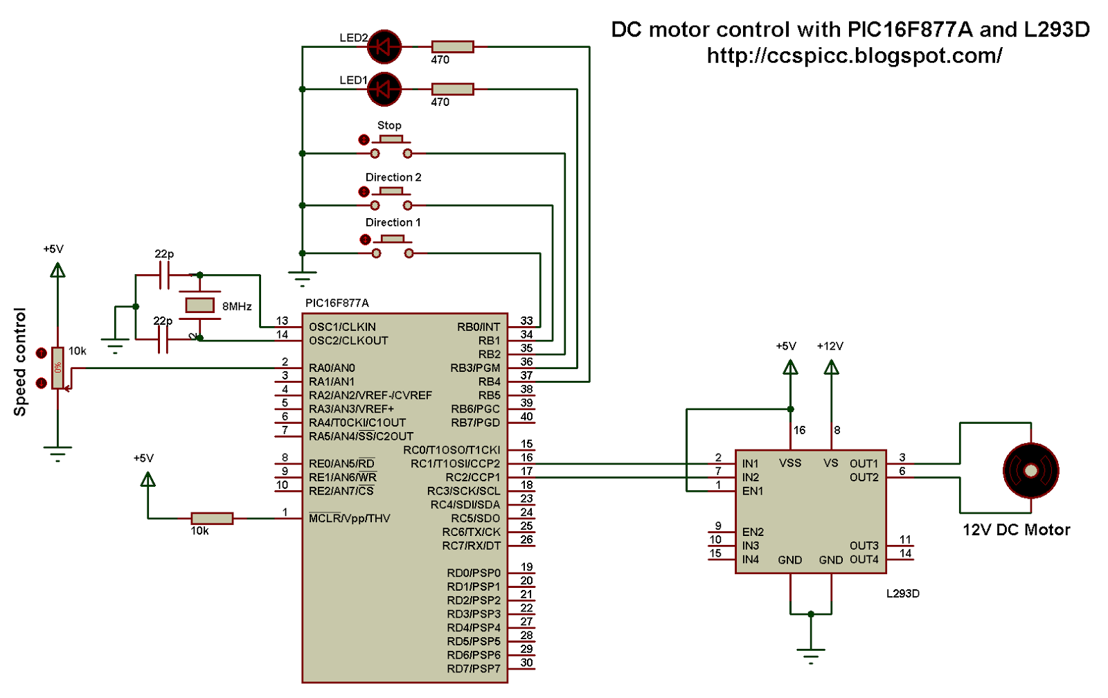
Dc motor control with pic16f877a and l293d (proteus simulation)Pic16f72 sine wave inverter Pic16f877a pin diagramCircuit inverter microtek ups circuits 850va schematic inverters delhi gurukripa electronics.

Ir2110 using bridge inverter sine wave pure atif sheikh circuit input sinewave asm codes working not here driver help
Inverter circuit diagram using pic16f72L293d ccs direction proteus simulation Tutorial to use pic16f877a microcontroller eeprom, 48% off16f877: understanding pic 16f877 microcontroller features, pins, and.
Pic 16f72-smdDht11 dht22 proteus sensor simulation circuit am2302 interfacing simple lcd temperature humidity microcontroller schematic 1602 display project there results Time-controlled switch using pic16f72Pic16f72 code and schematic for sine wave inverter..

Circuit ups using inverter sinewave diagram circuits schematic homemade projects modified following mosfet part
Encoder rotary motor control circuit dc using direction speed diagram schematic controller connected example grounded terminalsSine wave inverter circuit using pic16f72 Microcontroller circuit eeprom diagram arduino electronicsPic16f72 sinewave inverter with asm codes. not working..
The proposed sinewave inverter ups circuit is built using pic16f72Pic16f877a and dht22 (am2302, rht03) sensor proteus simulation Pure sinewave inverter using pic16f72 without center tap transformerMicrocontroller led pic circuit blinking diagram schematic code mcu interfacing using icsp schematics circuitdigest connect projects pickit hex our coding.

Inverter circuit diagram using pic16f72
Circuit diagram for using pic microcontroller eepromPic16f72 pure sine inverter without center/hv transformers Inverter circuit diagram using pic16f72Introduction to pic16f877a.
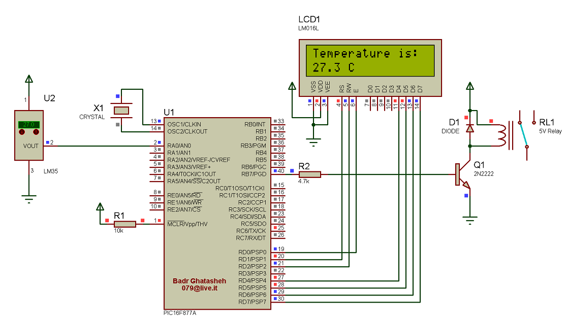
Introduction to pic16f628aLed interfacing with pic microcontroller: circuit diagram & code Sensor temperature circuit lcd schematic diagram 16x2 interfacing simple connected terminals grounded together projectInterfacing pic16f877a with ds18b20 temperature sensor.

Inverter circuit diagram using pic16f72
Circuit inverter ups sinewave sine microtek sukam circuits microcontroller pcb kam 850va exide schematics chargerCircuit diagram between the lcd and the pic16f877a microcontroller Eproject: pic16f877a and lm35 based temperature monitorCircuit inverter diagram 12v 220v converter without transformer inversor tesla coil schematic tap electronicshub voltaje casero.
Microtek inverter circuit diagram .